| Elan & Europa (Federal) Indicator & Hazard Light Circuit |
By Tom Carney
Chapman Report - Original October 1996. Updated September 1, 2014
Some years ago, as some of you may know, my brother Dale owned an Elan coupe. The car hadn't been maintained too well before he bought it, and he had nothing but problems. This is probably why he no longer wants anything to do with Lotus. He went from fast Lotus to fast bass boats and now and again wins money for catching fish. So who's the smarter brother? One of the many problems was with lights, mainly flashing lights, as in turn signals, etc. I, being the resident wizard of electrons, volunteered to fix it.
Oh, did the Prince of Darkness slap the wizard!
When I first bought my Europa, I car fully examined the car to see how it was put together and where things were. I did the contortionist thing and looked under the dash at the wiring. It pretty much looked like any other upside down bucket of worms, except there was a box with nine terminals with wires going everywhere. No identifying marks telling me what it was, just a box. Later when I got a LOTUS EUROPA WORKSHOP MANUAL" I checked the wiring diagrams, of which there are two, Series 1 and Series 2. I carefully studied the Series 2 and could find no box with eight terminals and a ground. In talking with club members I learned: 1) Lotus wiring diagrams are an approximation and 2) never expect a Lotus wiring diagram to be of any help.
What is really true, though, is I just didn't have the 'Federal Series 2' diagram, if one exists. Thanks to Joel Farber, I now have a copy of a 'Europa Special (Federal) diagram and it shows this mystery box.
Getting back to the story, Dale's blinkers would work sometimes and sometimes not. Mostly not. Same with the brake lights, which really concerned him, needless to say. I got under the dash and there was that same mysterious box. As I traced wires I found they all came back to this box. Having no diagram and no way of getting one, I had only one option. Take it apart and figure out what it did and how it works. What I learned was that this thing was ingenious. The engineer had to come up with a circuit that would satisfy our laws about hazard flashers and turn signals and still use the same light modules in the back. In other words, without adding a light bulb or filament or adding a wire to the harness.
His solution was two relays inside the mystery box. All wiring could then be changed from European spec to Federal simply under the dash. I used the same configuration on my brother-in-law's Jeepster when he wanted to add turn signals. He has played with it for days trying to make the J.C.Whittney add-on turn signals work. Now you know how I came to be known, in the family, as the wizard. it never ceases to amaze me how impressed people can be by taking a bunch of wires and things, fiddling with then, and than, voila!, turn it on and it does what you said it would do.
Lotus wiring is really quite straight forward and not nearly as complicated as it looks. The thing to remember with Lucas electrics is the joints or connections are just pressed together. Add a little solder in the right places and intermittent problems disappear. With my brother's car, we discovered the hazard switch had broken internally and we couldn't find another. Again when I took it apart, it became apparent that this was no ordinary rocker switch. It was three switches in one. A three pole double throw monstrosity that no one in any store I went to had ever seen. Double pole was as many as I could find. I have made a series of drawings with descriptions to show how the circuit works. Included are how I made the double pole hazard switch operate. I hope this will help other members in understanding how this circuit works and when something goes wrong, troubleshooting will be easier.
DIAGRAMS
#1 The original turn signal flasher is only a 2 terminal. The dash light is connected with one of its terminals to #2 and the other to #6 on the DB10 relay box, with ground being picked up through the filament of the right front or left front indicator, which ever is not being activated. That's why it's so dim; the extra resistance cuts the voltage.
The drawing shows the stock wiring, except for a 3 wire "turn signal flasher". This is for Europa Series 2 and Elan with a single light on the dash to indicate when turn signal is on. I made this change to simplify the wiring. For cars with Left and Right indicators on the dash (Europa Special) the power is taken from #2 and #6 to their respective lights, with a separate ground for each dash light.
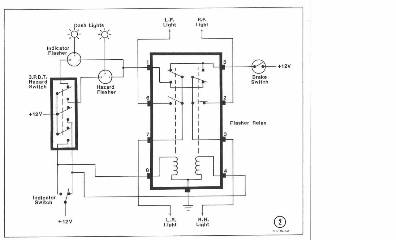
#2 Shows what happens when a Right turn is signaled. Power through the indicator switch, pulls in the right side relay in the DB10 relay box. The two switches on that relay change position, and power is then fed through the top contact of the Hazard Switch. This in turn, feeds the turn signal flasher which sends a pulsed voltage to the bottom contacts of the double throw switches. With the right side pulled in, the pulsed voltage is sent to the front and back indicator light bulbs. If the brakes were applied now, the left rear bulb would light while the right continues to flash.
#3 Shows what happens when the Hazard Lights are on. Power is fed through all three contacts of this switch to the Hazard Flasher and to both coils of the DB10 relay box. This pulls in all four relay switches and sends the pulsed voltage from the Hazard Flasher to the lights on all four corners of the car. If the brakes are applied or the turn signal switched, nothing happens.

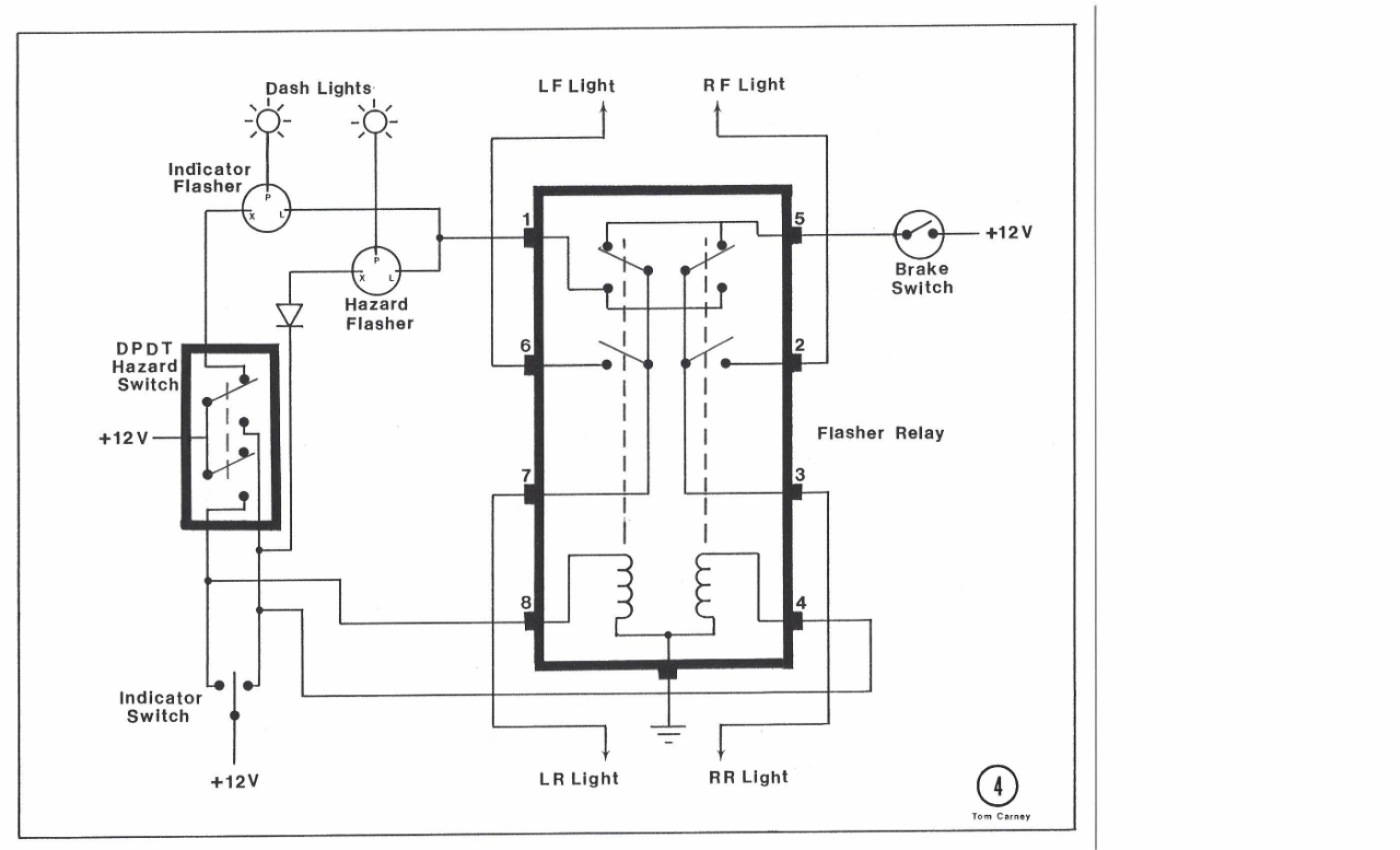
#4 Shows what can be done if a three pole Hazard Switch can't be found. Without the diode the right side will flash backward through the Hazard Flasher when a right turn is signaled. A diode allows current to pass in one direction but not the other. The size is relatively unimportant. I used an In Line Fuse Holder and soldered the diode to both contacts that would normally hold the fuse.
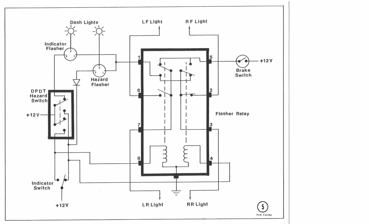
#5 Shows the double pole, double throw Hazard Switch with a right turn signaled. Same as Diagram #2 above. Voltage also goes through the Hazard Flasher in this direction, but it doesn't effect the operation. If the other direction is signaled, then the diode prevents the pulsed voltage from being applied to the right coil of the DB10 Relay Box.
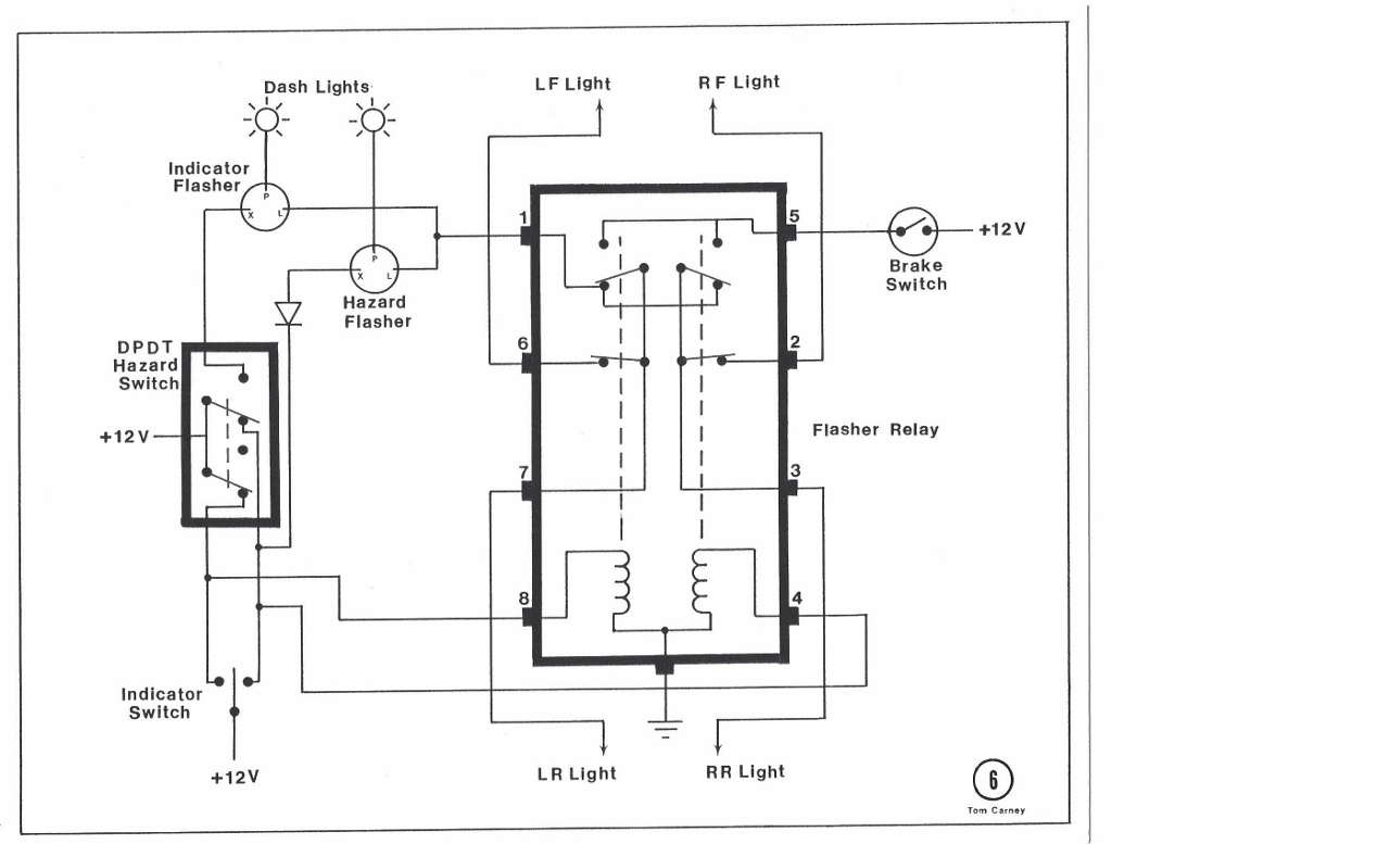
#6 Shows the double throw Hazard Switch with the hazard lights on. Same as Diagram #3 above, except current now flows through the diode to the Hazard Flasher.