| Lotus 26R Handling & Maintenance Notes |
HANDLING AND MAINTENANCE NOTES FOR THE RACING VERSION OF THE LOTUS ELAN S.2
Lotus Components Racing Division, Delamare Road, Cheshunt, Herts.
Telephone: Waltham Cross 26181
April 1965
GENERAL DIMENSIONS
|
Racing Version |
Stock |
|
|
Wheelbase |
84 inches |
|
|
Track, front |
45 ỳ" |
47.094" |
|
Track, rear |
49 ỳ" |
47.06" |
|
Length overall |
145" |
|
|
Width overall |
56" |
|
|
Height overall |
46" |
46.5" |
|
Fuel tank |
10 Ẅ gallons |
|
|
Extra tank |
12 Ẅ gallons |
|
|
Spring rate, front |
128 lbs/in |
75 lb/in |
|
Spring rate, rear |
100 lbs/in |
67.5 lb/in |
|
Anti roll bar, front |
13/16" |
|
|
Anti roll bar, rear |
Ẅ" |
None |
|
Ground clearance to bottom of chassis |
5" |
6" |
REAR AXLE
The car should be driven gently, initially, for as far as practical in order to run in the rear axle; if the axle is not run in it will rapidly become noisy and wear out prematurely Recommended oil Esso AL1763.
Inspect the limited slip diff. Regularly by its very function it cannot be expected to last forever.
ENGINE
BRM Type 84 (see separate schedule)
CLUTCH
Borg and Beck 8" diaphragm type
GEARBOX
|
Ratios |
Standard |
Alternative |
|
1st |
2.509 |
3.543 |
|
2nd |
1.64 |
2.396 or 2.04 |
|
3rd |
1.230 |
1.412 |
|
Top |
1.00 |
1.00 |
|
Reverse |
2.807 |
3.960 |
Recommended oil: Esso GP.80 or equivalent
FINAL DRIVE
Aluminum alloy differential carrier in magnesium housing fitted with limited slip differential.
|
Alternative Ratios |
4.43 |
4.12 |
3.90 |
|
Speed at 7000 rpm in top |
117 mph |
126 mph |
133 mph |
Recommended oil: Esso AL.1763
Calculated when fitted with 600 x 13 tyre (807 revs. Per mile)
If the unit is stripped, care should be taken to see that the correct thickness of gasket is used.
DRIVE SHAFTS
The frictionless roller splines which make up the driveshafts on this car are manufactured to very fine tolerances and the dust seals should be kept in perfect condition and the shafts checked for grease at least twice a season. Care should be taken when dismantling to avoid loss of any of the rollers.
If the car is raced in wet conditions the drive shafts should be dismantled immediately afterwards, repacked with grease and the felt seal replaced.
SUSPENSION
The suspension should be set at the running ground clearance of 5".
|
Camber |
Front Rear |
1° negative 2° negative |
|
Toe-in |
Front Rear |
1/8" total 3/8" total |
|
Dampers |
Front Rear |
18 clicks from soft non-adjustable |
|
Tyre Pressure |
Front Rear |
32 lbs./sq in cold 32 lbs./sq in cold |
|
Castor |
Front |
3° |
The toe-in at the front should also be checked with the car in full bump and full rebound positions. It is permissible to have up to 1/8" more toe-in on rebound than bump. Variations greater than above can be corrected by adjusting the spacers under the steering rack clamps.
Raising the rack by 1/16" on one side will produce about 3/32" more toe-in on rebound than bump on that side.
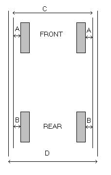
Wheel alignment may be carried out as follows:
Set two bars at hub height, one at each side of the car, so that "C" and "D" are equal and "A" equals "A" and "B" equals "B", then set front and rear wheels as follows:
|
Front: |
1/16" toe in on each wheel measured on the rim at the side wall with the steering wheel central. |
|
Rear: |
3/16" on each wheel measure as above. |
ROSE BEARINGS
These should be cleaned, checked and regreased at regular intervals as they are inclined to pick up grit and subsequently seize.
WHEELS
Magnesium knock-on wheels of 6" rim width.
The left (crossed out and "right" is written in) hand threaded hubs should be fitted on the right hand side of the car. To ensure that the wheel does not loosen, the friction between the nut and the hub should be greater than the friction between the nut and the wheel. The threads, therefore, should be kept dry and the cone on the nut lightly coated with molybdenum disulphide.
Tyres:
|
Front: |
5.50 x 13 R6 |
|
Rear: |
6.00 x 13 R6 |
BRAKES
The master cylinders are 5/8" bore, the front calipers are Girling Type AR and the rear calipers are Girling Type 10/12 HP.
Care should be taken to see that the flexible brake pipes have a free run (particularly near the rear wheel). The run of the pipe can be altered by rotating the inboard end of the flexible pipe before tightening.
The pad material used in Ferodo DS.11.
The braking system is fitted with twin master cylinders, both cylinders being 5/8" bore. The two master cylinder push rods are connected to a adjustable balance bar to enable adjustment of ratio between front and the rear to be obtained.
Adjust balance bar:
COOLING SYSTEM
An aluminum radiator block is used with a remote header tank. The radiator is of very light construction and great care should be taken when handling it. Particular care should be taken to see that the bottom intake does not touch the body when the radiator is fixed, otherwise the tank will squash and leak. The radiator is mounted at a small angle as viewed from the front to give adequate clearance between the inlet and the bonnet lid.
In standard form the engine gives approximately 105 bhp, but when modified by the BRM Engine Development Division of Rubery Owen & Co. Ltd. Gives a minimum of 145 bhp. It is vital that the engine number is quoted when ordering spares.
OVERALL SPECIFICATION
|
Capacity: |
1594 cc (97.4 cu. In) |
|
Bore: |
83.5mm (3.288") |
|
Stroke: |
72.55mm (2.864") |
|
Compression ratio: |
11:1 |
|
Maximum bhp: |
145 minimum at 6,750 rpm |
|
Maximum torque: |
130 lbs. Ft. at 5,000 rpm |
|
Maximum BMBP |
201 psi at 5,000 rpm |
|
Maximum rpm |
7,000 rpm |
CYLINDER HEAD
Cast aluminum twin overhead camshaft hemispherical head. Valves set at included angle of 54°
CRANKSHAFT / FLYWHEEL CLUTCH
Cast iron crankshaft and flywheel with diaphragm type clutch. Whole assembly dynamically balanced before assembly.
TIMING COVER ASSEMBLY
Cast aluminum timing case and cover mounted on front of the cylinder block enclosing camshaft drive system by Renolts Chain 3/8" pitch, chain tension controlled by spring loaded jockey pulley tensioner unit on one side of engine and rubber damper on opposite side. Timing chain also drives jackshaft incorporating skew gear for distributor and oil pumps.
MAIN AND BIG END BEARINGS
Vanderwell lead Indium bearings. Steel backed.
PISTONS AND CON RODS
Die cast piston with Ford steel conn rod (125B) two plain compression rings and one four piece steel oil control. Ring diametral clearance of skirt 0.006" 0.008". Ring gaps 0.016 / 0.021.
VALVES
Inlet 1.53" dia. 5/16" stem 45°
seat angle mat: - EN52
Exhaust 1.32" dia. 5/16" stem 45° seat angle mat: EN59
VALVE SPRINGS
Special BRM racing springs to BRM specification. A.7005 Inner and A.7004 outer. Free lengths 1.426" inner; 1.400" outer.
VALVE TIMING
|
Inlet valve opens |
54° BTDC |
|
Inlet valve closes |
82° ABDC |
|
Exhaust valve opens |
72° BBDC |
|
Exhaust valve closes |
54° ATDC |
Based on tappet clearances of 0.009" exhaust 0.006" inlet and using 0.002" shim foil for timing (see over).
LUBRICATION SYSTEM
Wet sump engine with standard Ford oil pump and filter but fitted with high rate oil pressure relief valve spring.
IGNITION SYSTEM
Coil ignition, firing order: 1 3 4 2
Centrifugal ignition advance, giving 24° crankshaft advance
Standard contact breaker points 18 24 oz. Spring.
Static ignition setting 14° BTDC
Contact breaker gap 0.012"
(Static timing may be changed during dynamometer running)
MAXIMUM SAFE REVS
7,000 r.p.m.
FUEL SYSTEM
Supply drawn from Bendix high pressure type 12 volt pump.
If it is ever necessary to replace the clutch pressure plate assembly, the new one must be balanced on the crankshaft / flywheel assembly and marked to ensure correct refitting thereafter.