I recommend another person or a small clamp. I also recommend ratcheting wrenches to speed things up.
1. Remove the stock air inlet tube. This is the rubber tube going from the air box to the intake manifold. Using a flat screwdriver, loosen the stainless steel clamps on both ends. Once loose enough, pull away from the manifold and then the air box. The inlet tube and the clamps will not be re-used.
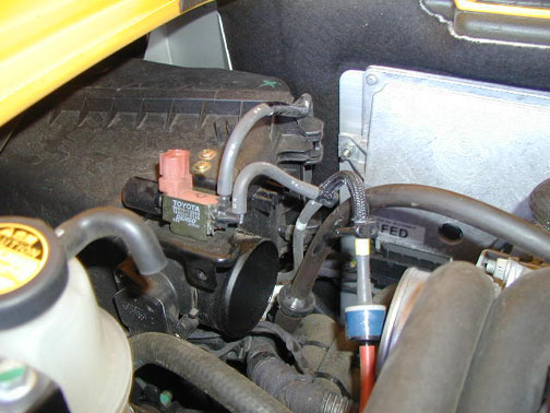
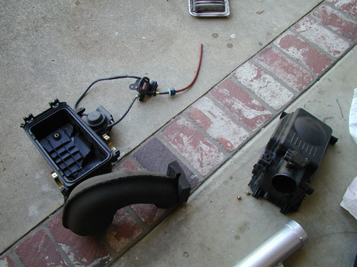
2. Unplug the VSV connector. Always use care when removing the connectors. Depress the tab on the side to unlock the connector and then remove the mating part. The VSV is the module with the orangish connector in the next picture. Here you see the intake tube has been removed, and the mating connector from the VSV has also been removed.
3. Unplug the mating connector to the MAF (Mass Air Flow sensor). This is the black squarish device located on the air box. The connector is longer and has a similar locking tab on the side.
4. Remove both vacuum lines going to the VSV. You may find it easier to use a combination of gentle pulling and a flat bladed screwdriver to get the tubes to release.
5. In the above picture, you can see a "T" fitting on the vacuum lines. There is a small rubber plug on one port on the "T." The vacuum lines are either going to the airbox, or they were from the VSV. One line was going to the engine. Remove that line from the engine and using the rubber cap you just removed, cap off the engine vacuum port. The rest of the vacuum lines and fittings you removed will not be re-used.
6. Using the factory jacking point, jack up the car to gain access to the rear driver's side wheel. Remove wheel from car. You may want to use a jackstand or some other method to insure your safety. You will not be working under the car, but you will be working inside the rear wheel well.
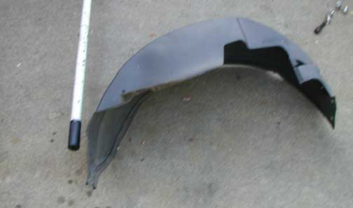
7. Remove the wheel well splash guard. This is held on with 7 plastic screws. You will probably have to also remove (pull out) the mating plastic fasteners, specially the front two. Once all screws have been removed, the trick is to bend it away from the lip of the wheel well and then extract the entire piece.
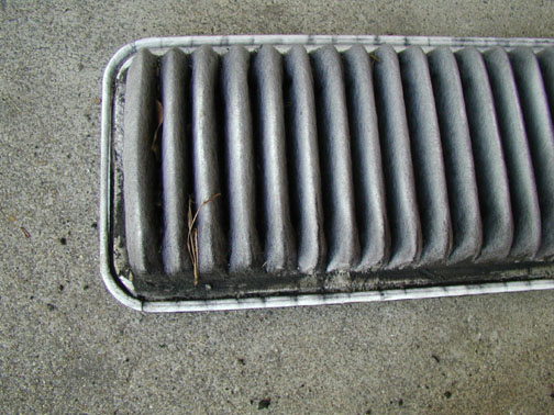
8. From inside the wheel well, reach up and unclip the clips that hold on the airbox cover. Remove this cover and the air filter inside. You will not be reusing these.
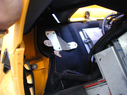
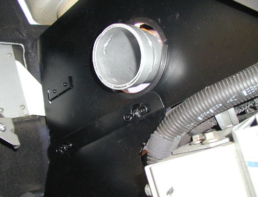
9. From the engine bay side, remove the three 13mm hex bolts that hold the air box base to the bracket on the engine firewall. This requires some dexterity and different tools. A 13mm socket on an extension is best for the most visible bolt. Remove the air box base. Set aside the three bolts. You will not be reusing these parts, except for one 13mm bolt.
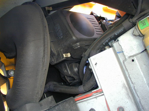
This is what it looks like now, looking up from the wheel well.
10. Remove the MAF from the stock air box. There are two very small phillips screws. You will not be reusing the screws.
11. Unpack the new Intake Tube. Make sure the two brass hex standoffs are securely tightened down by using a wrench on them. Temporarily remove the two small allen head bolts that are threaded into the brass standoffs.
12. Install the MAF into the Intake Tube. Note orientation of the MAF. It will obviously fit one way. Using the two allen head bolts and an Allen wrench, tighten the MAF so that it sits flush on the Intake Tube. Set the Intake Tube aside.
(here things get a little interesting)
13. Unpack the heat shields. There are two black sheetmetal parts that are connected with two DZUS fasteners. If these are together, separate them now.
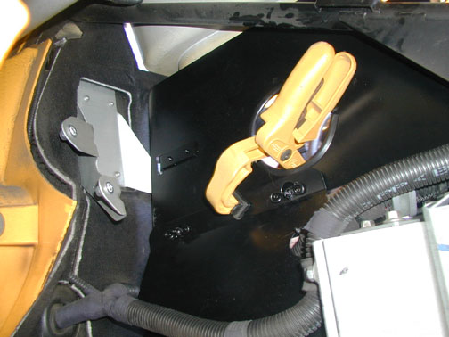
14. From the wheel well side, roughly fit the small heat sheild into position. It will sort of wedge in there. The two DZUS fasteners will be towards the top. The shield's bend will be towards you and the shield will sit at an angle with the two rounded openings or reliefs on the sides going around the tubes and harness bundles.
15. Remove the two bolts holding on the engine coolant reservoir. One bolt is accessed from the engine bay side easily using a 10mm wrench. The other is accessed from the wheel well side. Unbolt that one from the top using an 8mm (I think) wrench. Carefully set aside these two bolts. From the engine bay side, pull the coolant reservoir away from its mounting points. Leave all tubes attached. You will only need to just pull the reservoir aside a short distance.
16. Now place the upper shield in the engine compartment (working from engine bay side). This will take a bit of angling in to get it in. Roughly place it where it will end up. The mounting tab will be near the 13mm bolt mounting hole for the stock air box. I recommend lining up this hole and then starting to thread in the 13mm bolt. Do not fully install this bolt yet.
17. Now line up the DZUS fasteners on both the upper and lower shields. This is tricky to do and to also have access to the turning side of the fasteners. I found I could turn them with either my fingers or the edge of a dime. It may take a second person to hold things or to have three hands. My solution which worked a treat, was to use a small clamp to hold things in alignment, and then I would go to the engine bay side and tighten the fasteners (one at a time).
ForcedFed's instructions take note that you may have to reroute some coolant or wiring harness bundles, but I found I did not have to do any of that.
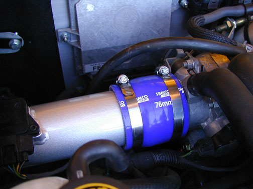
18. Back to that new Inlet Tube. Slide one of the new stainless steel clamps onto the throttle body end. This is the end farther away from the MAF. Slide a silicone coupler onto that same end, making sure it extends well past the band on the end of the tube.
19. Place the other band on the tube on the throttle body. Check placement of bands so that you have easy access to the tightening screws. You may have to loosen up the bands before installing.
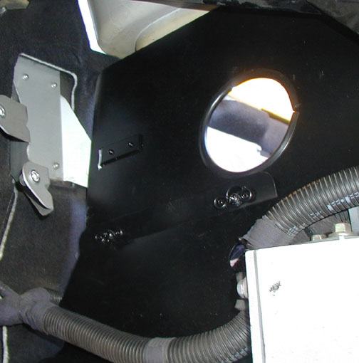
20. Insert the end of the Intake Tube without a silicone coupler into the hole in the new heat sheild. Slide the Intake Tube with the silicone coupler over the throttle body, sliding the stainless steel clamp over the coupler. Adjust band positions and then tighten using a flat screwdriver or a hex nut driver.
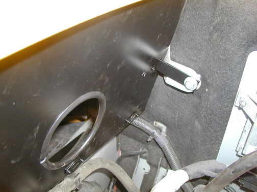
21. Going through the wheel well, install a stainless steel band and then a coupler onto the exposed end of the Intake Tube.
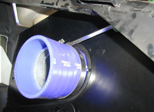
Note location of screwdriver and position of clamp tightening fasteners. I found you can gain access to this screw from around the suspension bits quite nicely. I also found that after initial tightening with a flat screwdriver, that I preferred final tightening with a nut driver. In my kit, to my surprise, the 4 bands required two different socket sizes.
Almost done!
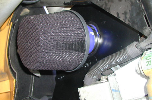
22. Install the last stainless steel band clamp onto the exposed end of the silcone oupler. Install new air filter by pushing into the coupler. Align band and tighten well.
23. Position the coolant reservoir back to where it was and tighten the two bolts.
24. Install the removed wheel well liner.
25. Put the rear wheel back on the car using standard procedures. Lower the car. Torque the lug nuts!!!
26. Plug the connector into the MAF.
27. Remove the VSV from the stock air box using the two screws.
28. Plug the VSV back into its connector. Zip tie the VSV to somewhere in the engine compartment. I used the vertical metal bracket for the coolant reservoir.
29. Close the boot. Put away the tools. Place all the stock items no longer being used in a container so they won't be lost.
30. Drive.
31. BIG GRIN
My thoughts about the CAI and the install.